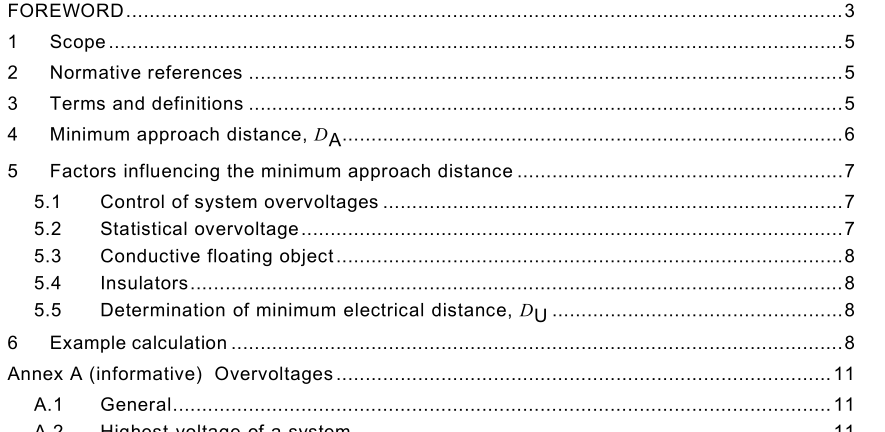
IEC 61472-2-2021 pdf Live working – Minimum approach distances – Part 2: Method of determination of the electrical component distance for AC systems from 1,0 kV to 72,5 kV

3.1 highest voltage of a system U s highest value of operating voltage (phase-to-phase voltage) which occurs under normal operating conditions at any time and any point in the system Note 1 to entry: Transient overvoltages and permanent induction from adjacent lines are not taken into account in the calculation formula
3.2 transient overvoltage short duration overvoltage of a few milliseconds or less, oscillatory or non-oscillatory, usually highly damped [SOURCE: IEC 60050-61 4:201 6, 61 4-03-1 4] 3.3 nominal system voltage suitable approximate value of voltage used to designate or identify a system [SOURCE: IEC 60038:2009, 3.1 ] 3.4 per unit statistical overvoltage phase-to-earth u e2 phase-to-earth per unit overvoltage that has a 2 % probability of being exceeded 3.5 per unit statistical overvoltage phase-to-phase u p2 per unit overvoltage that has a 2 % probability of being exceeded 3.6 statistical overvoltage U 2 overvoltage that has a 2 % probability of being exceeded 3.7 minimum approach distance D A minimum electrical and ergonomic distance in air to be maintained between any part of the body of a worker, or any conductive tool being directly handled, and any live conductors or equipment at different potentials 3.8 electrical distance D U electrical component of the minimum air distance between two electrodes which represent live and/or earthed conductors or equipment, required to prevent sparkover under the most severe electrical stress that will arise under the chosen conditions 3.9 ergonomic distance D E distance in air added to the electrical distance, to take into account inadvertent movement and errors in judgement of distances while performing work [SOURCE: IEC 60050-651 :201 4, 651 -21 -1 3, modified – the symbol D E has been added.]
5 Factors influencing the minimum approach distance 5.1 Control of system overvoltages The maximum amplitude of overvoltages in the work area can be reduced by the usual practice of making the circuit-breaker reclosing devices inoperative, or by using protective gaps or surge arresters.
5.5 Determination of minimum electrical distance, D U The minimum electrical distance is determined from the impulse rod-to-rod withstand voltage of IEEE 51 6-2009, Table 1 , and presented in Table 2 and Table 3. For systems using other per unit overvoltage factors the minimum electrical distance may be derived from Table 1 using linear interpolation.
- Previous:IEC 61587-6-2021 pdf Mechanical structures for electrical and electronic equipment – Tests for IEC 60917 and IEC 60297 series – Part 6: Security aspects for indoor cabinets
- Next:IEC 61468-2021 pdf Nuclear power plants – Instrumentation systems important to safety – In-core instrumentation: Characteristics and test methods of self-powered neutron detectors
- ISO IEC 27050-4-2021 pdf Information technology — Electronic discovery — Part 4: Technical readiness
- ISO IEC 27036-1-2021 pdf Cybersecurity — Supplier relationships — Part 1: Overview and concepts
- ISO IEC 27013-2021 pdf Information security, cybersecurity and privacy protection — Guidance on the integrated implementation of ISO/IEC 27001 and ISO/IEC 20000-1
- ISO IEC 26580-2021 pdf Software and systems engineering — Methods and tools for the feature- based approach to software and systems product line engineering
- ISO IEC 24735-2021 pdf Information technology — Office equipment — Method for measuring digital copying productivity
- ISO IEC 24711-2021 pdf Information technology — Office equipment — Method for the determination of ink cartridge yield for colour inkjet printers and multi- function devices that contain printer components
- ISO IEC 23544-2021 pdf Information Technology — Data centres — Application Platform Energy Effectiveness (APEE)
- ISO IEC 23510-2021 pdf Information technology — 3D printing and scanning — Framework for an Additive Manufacturing Service Platform (AMSP)
- ISO IEC 23127-1-2021 pdf Information technology — Learning, education, and training — Metadata for facilitators of online learning — Part 1: Framework
- ISO IEC 23126-2021 pdf Information technology for learning, education and training — Ubiquitous learning resource organization and description framework
- IEC 63002-2021 pdf Interoperability specifications and communication method for external power supplies used with computing and consumer electronics devices
- IEC 61500-2009 pdf Nuclear power plants – Instrumentation and control important to safety – Data communication in systems performing category A functions
- IEC 61251-2015 pdf Electrical insulating materials and systems – AC voltage endurance evaluation
- IEC 61587-6-2021 pdf Mechanical structures for electrical and electronic equipment – Tests for IEC 60917 and IEC 60297 series – Part 6: Security aspects for indoor cabinets
- IEC 60050-902-2013 pdf International electrotechnical vocabulary – Part 902: Conformity assessment
- BS ISO IEC 15420-2009 pdf Information technology一 Automatic identification and data capture techniques EAN/UPC bar code symbology specification
- BS IEC 60860-2014 pdf Radiation protection instrumentation一 Warning equipment for criticality accidents
- BS ISO IEC 19762.5-2008 pdf Information technology一 Automatic identification and data capture (AIDC) techniques – Harmonized vocabulary Part 5: Locating systems
- ISO IEC 24735-2021 pdf Information technology — Office equipment — Method for measuring digital copying productivity
- ISO IEC 24711-2021 pdf Information technology — Office equipment — Method for the determination of ink cartridge yield for colour inkjet printers and multi- function devices that contain printer components