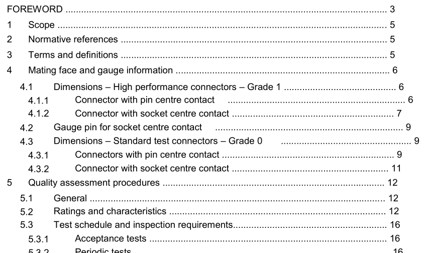
IEC 61169-15-2021 pdf Radio-frequency connectors – Part 15: Sectional specification – RF coaxial connectors with inner diameter of outer conductor 4,13 mm (0,163 in) with threaded coupling – Characteristic impedance 50 Ω (type SMA)

1 Scope This part of IEC 61169, which is a sectional specification (SS), provides information and rules for the preparation of detail specifications (DS) for RF coaxial connectors with inner diameter of outer conductor 4,13 mm (0,163 in) with threaded coupling with a characteristic impedance of 50 Ω (type SMA). This document specifies mating face dimensions for high performance connectors – grade 1, dimensional details of standard test connectors – grade 0, gauging information and tests selected from IEC 61169-1, applicable to all detail specifications relating to series SMA RF connectors. This document indicates recommended performance characteristics to be considered when writing a detail specification and it covers test schedules and inspection requirements for assessment levels M and H. The SMA types RF coaxial connectors are used with all kinds of RF cables and microstrips in microwave transmission systems. The operating frequency is up to 18 GHz. These connectors can be intermated with 3,5 mm (IEEE 287-2007) and 2,92 mm (IEC 61169-35) connectors. NOTE Metric dimensions are original dimensions. All undimensioned pictorial configurations are for reference purpose only. 2 Normative references The following documents are referred to in the text in such a way that some or all of their content constitutes requirements of this document. For dated references, only the edition cited applies. For undated references, the latest edition of the referenced document (including any amendments) applies. IEC 61169-1:2013, Radio frequency connectors – Part 1: Generic specification – General requirements and measuring methods IEC 62153-4-7:2015, Metallic communication cable test methods – Part 4-7: Electromagnetic compatibility (EMC) – Test method for measuring of transfer impedance Z and screening T attenuation a or coupling attenuation a c of connectors and assemblies up to and above s 3 GHz – Triaxial tube in tube method
The test procedure is as follows: a) Sizing test The gauge A shall be inserted into the socket-centre contact three times. This is a sizing operation and should only be carried out when the socket-centre contact is removed from the connector. b) Insertion test Following the sizing operation, and if required in the detail specification, the force necessary to insert gauge B fully into the socket-centre contact shall be measured. When this test is required, the maximum permitted insertion force shall then be specified and shall not exceed 13,3 N. c) Retention test After the sizing test, the gauge B shall be inserted into socket-centre contact. The contact shall retain the mass of the gauge B in a vertical downward position.
- ISO IEC 27050-4-2021 pdf Information technology — Electronic discovery — Part 4: Technical readiness
- ISO IEC 27036-1-2021 pdf Cybersecurity — Supplier relationships — Part 1: Overview and concepts
- ISO IEC 27013-2021 pdf Information security, cybersecurity and privacy protection — Guidance on the integrated implementation of ISO/IEC 27001 and ISO/IEC 20000-1
- ISO IEC 26580-2021 pdf Software and systems engineering — Methods and tools for the feature- based approach to software and systems product line engineering
- ISO IEC 24735-2021 pdf Information technology — Office equipment — Method for measuring digital copying productivity
- ISO IEC 24711-2021 pdf Information technology — Office equipment — Method for the determination of ink cartridge yield for colour inkjet printers and multi- function devices that contain printer components
- ISO IEC 23544-2021 pdf Information Technology — Data centres — Application Platform Energy Effectiveness (APEE)
- ISO IEC 23510-2021 pdf Information technology — 3D printing and scanning — Framework for an Additive Manufacturing Service Platform (AMSP)
- ISO IEC 23127-1-2021 pdf Information technology — Learning, education, and training — Metadata for facilitators of online learning — Part 1: Framework
- ISO IEC 23126-2021 pdf Information technology for learning, education and training — Ubiquitous learning resource organization and description framework
- BS ISO IEC 15420-2009 pdf Information technology一 Automatic identification and data capture techniques EAN/UPC bar code symbology specification
- IEC 60317-36-2013 pdf Specifications for particular types of winding wires – Part 36: Solderable polyesterimide enamelled round copper wire, class 180, with a bonding layer
- ISO IEC 19770-11-2021 pdf Information technology — IT asset management — Part 11: Requirements for bodies providing audit and certification of IT asset management systems
- IEC 60358-3-2013 pdf Coupling capacitors and capacitor dividers – Part 3: AC or DC coupling capacitor for harmonic-filters applications
- IEC TS 62796-2013 pdf Energy efficiency in electroheating installations
- BS ISO IEC 15420-2009 pdf Information technology一 Automatic identification and data capture techniques EAN/UPC bar code symbology specification
- BS IEC 60860-2014 pdf Radiation protection instrumentation一 Warning equipment for criticality accidents
- BS ISO IEC 19762.5-2008 pdf Information technology一 Automatic identification and data capture (AIDC) techniques – Harmonized vocabulary Part 5: Locating systems
- ISO IEC 24735-2021 pdf Information technology — Office equipment — Method for measuring digital copying productivity
- ISO IEC 24711-2021 pdf Information technology — Office equipment — Method for the determination of ink cartridge yield for colour inkjet printers and multi- function devices that contain printer components